Exercise: Hello Grasshopper (1/2)
Step 1: Define the base point.
We need somewhere to start with our definition. A good place to start is defining a location where our circle geometry will be generated. We can do this using a point object, which defines a location in space based on its x, y, and z coordinates.

To define a point in Grasshopper we can use the Point component. This defines a point in Grasshopper by referencing a point already in the Rhino model or by creating one directly in Rhino. To place the point on the canvas, click the component in the toolbar, and while holding down the mouse button drag it onto the canvas. Release the mouse button to place the component on the canvas.
When you first place the component on the canvas it will be colored orange, which tells you that there is some kind of warning being generated by the component. In this case, it’s because we haven’t yet defined a point for the component, so let’s fix that in the next step.
Right-click on the Point component and select ‘Set One Point’. This will switch you over to the Rhino interface and ask you to select a location for the Point. Look at the command line and make sure the option for selecting the location is set to ‘Coordinate’. This will allow you to pick the location dynamically by clicking in the Rhino viewport. You can also type “0” and hit Enter to place the point at the model’s origin.
Once you place the point, you will be taken back to the Grasshopper canvas, where the component has now turned the default light grey color. You will also see a red cross in the Rhino viewport representing the location of the point defined in Grasshopper. Remember that this is just a visualization of the point, which only exists in Grasshopper and does not exist in the actual Rhino model. If you click on the Point component you will see a widget displayed over the point in Rhino which allows you to change its position interactively.
Step 2: Create a circle
Now that we have a point to work from, let’s use it to create a circle. To make sure you see the circle geometry properly, switch to either the Top or a 3d viewport in Grasshopper, centered on the point we just created.

To create a circle, we need to find the right component in the toolbar. Grasshopper actually has several different components for creating circles, which can be found in the ‘Primitive’ section of the ‘Curve’ tab five over from the left. The one you choose depends on how you want the circle to be generated. In our case, we will use the Circle CNR component, which generates a circle based on its Center-point, Normal vector, and Radius (CNR).
Drag a Circle CNR component out to your canvas and place it to the right of the Point component. As before, the component is orange because we have not supplied it with the data it needs to generate its output. To make the component work we need to supply this data through its input ports.
Let’s start by defining the circle’s center point by connecting the output port of the Point component to the ‘C’ input port of the Circle CNR component. When these components are connected, the point geometry stored in the Point component ‘flows’ to the Circle CNR component, where it is used to specify the center point of the circle created. It is important to understand that the geometry does not physically move between the components. The point geometry is still stored in the Point component, but is referenced by the Circle CNR component when it performs its task.
Once we define the circle’s center point, the Circle CNR component turns grey and you should see a red circle appear around your point in the Rhino viewport. The component is able to run and generate the circle geometry even though we did not supply the second and third inputs. This is because it has default values for those inputs stored within the component.
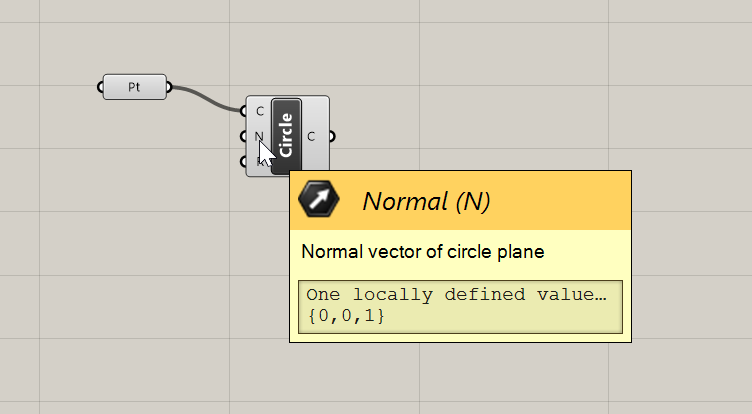
You can see these default values by hovering over the labels of the inputs. In this case, the component is using a unit Z vector as the default normal vector, and ‘1’ as the radius. We will discuss vectors in more detail in a later lesson so we won’t worry about it for now and leave the default Normal vector as it is.

To control the size of our circle interactively, let’s connect the Circle CNR component’s ‘R’ input to a Number Slider. You can find the Number Slider in the ‘Input’ section of the ‘Params’ tab, first from the left. Place a Number Slider component below the Point component on the canvas and connect it to the Circle CNR component’s ‘R’ input. You can now change the value of the Number Slider and see the circle changing size dynamically in the Rhino viewport. Since the range of the slider is set to 0–1 by default, you may have to zoom in on your viewport to see the circle.