Exercise: Parametric facade (2/4)
Step 3: Create the panels

Now that we have the Points, we need to define the actual panel geometries based on those Points. To create a Surface object from four corner Points, we can use the 4Point Surface component. This component has four individual inputs where we can connect the four corner Points to create a Surface. We can create all the panels of our building at once by supplying a list of Points to each input, but the lists have to be aligned so that the right Points are available for each panel as it’s being created.
Currently, we have two Lists of Points defining the upper and lower corners of each panel. If we iterate through each list simultaneously, this will give us the leading two Points of each panel. To define the other two points, we can actually reuse the same Lists of Points, since the trailing points of one panel become the leading points of the next.

However, to make sure the right points align for each panel, we first need to shift the Lists by one spot, so that the first panel actually gets the second point from each new List. To shift the Lists we can use the Shift List component, which will shift the items in a List to the left by the number of spots indicated in its Shift (S) input. Let’s create two new Shift List components and connect their (L) inputs to the outputs of the Divide Curve and Move components that are storing our point data.
The Shift List component’s Shift (S) input is set to 1 by default, which will shift the List one spot to the left, meaning the second item will now become the first. Since this is exactly what we want, we can leave the default value. Once the definition is complete, feel free to experiment with this input to see how the shift factor affects the way the panels are created. You can also try inputting negative values to shift the List in the other direction.

Now that we have our four sets of points for the four corner points of each panel, we can connect them to the 4Point Surface component. This component expects you to enter the corner points in counter-clockwise order. Based on the following diagram we can connect the original Points to the (A) input, the shifted version of the original Points to the (B) input, the shifted version of the moved Points to the (C) input, and the moved Points to the (D) input.
When everything is properly connected you should see the flat panel geometries appear properly in the model. If you don’t see the panels or they appear twisted you may have input them in the wrong order. Make sure your solution matches the image below.
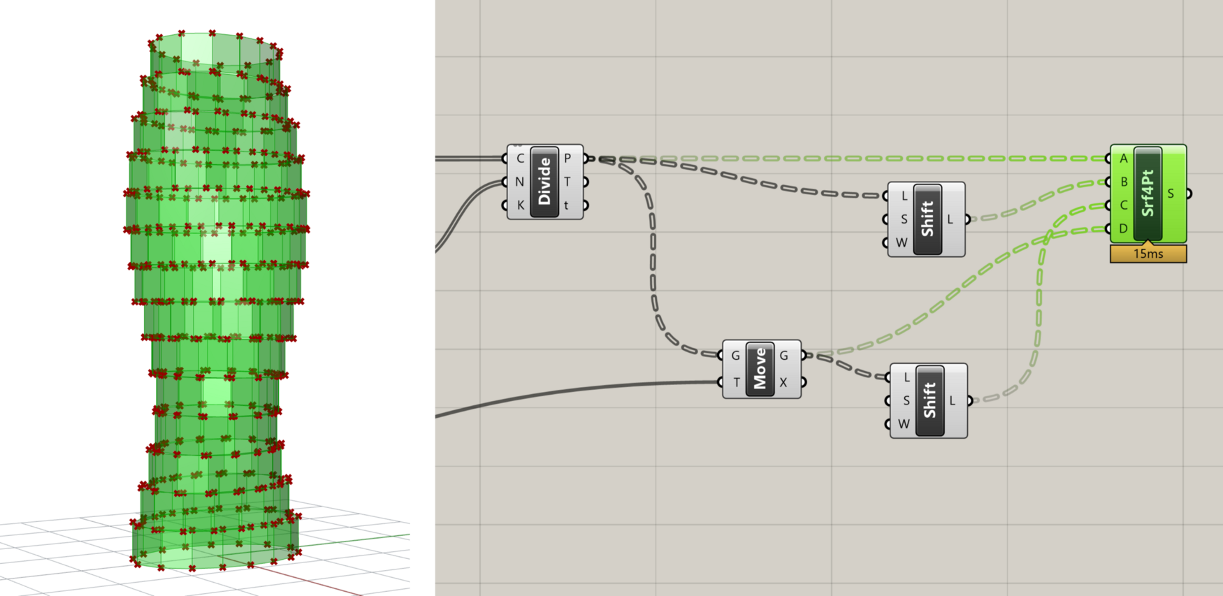
Panel geometries created by the 4Point Surface component
You’ve probably noticed that the Shift List components also have a third input called Wrap (W) which specifies whether the elements moved off the end of the list should wrap around and be placed at the other end. In our case, we will leave this at the default ‘True’ because we want the first points in each list to wrap around to the end of the shifted Lists so they can be used to create the last panel on each floor. Try to set these to ‘False’ and you will see that the last panel on each floor will not be created correctly.
Step 4: Create openings

Now that the basic panels are created, let’s add some detail by creating an opening in each panel. Our strategy for creating the openings will be to first scale each surface to make a smaller surface, then extract the edges of both surfaces and use the edges to construct a single surface with a hole in it.

To scale the surfaces, we will use the Scale component, which scales an object based on a center point and scale factor. Place a new Scale component on the canvas and connect its (G) input to the panel surfaces stored in the (S) output of the 4Point Surface component. This will create a half-size version of the tower since the default scale factor is 0.5 and the default center point for scaling each panel is the model origin.

To scale each panel relative to its own center point, we need to first generate a set of Points at the panel centers and then pass these points to the Scale component. A good way to get the center point of a flat object such as a surface or closed curve is to use the Area component, which will compute the area of the object as well as its centroid.
Let’s create a new Area component and connect it to the panel Surfaces. You should see a Point object appear in the model at the center of each panel. Now let’s pass this List of Points to the (C) input of the Scale component. Each surface should now be scaled relative to its own center, with a smaller surface sitting on top of the original one. Since we’re using the same Surfaces we’re scaling to generate the center points, we can be sure that the number of Surfaces and Points will match and that the right Point will be used to scale each Surface. To finish things off, let’s make a new Number Slider component and connect it to the (F) input of the Scale component so we can control the scale factor (and thus the size of the openings).